Instructions
Snow Guard Installation Video:
In this video, you'll learn three ways to install SnoBlox-Snojax Snow Guards on metal roofs.
- By adhesive attachment using Surebond SB-190 adhesive,
- By mechanical attachment using #14 screws, and
- By 3m tape attachment.
Start by getting a free custom spacing layout from SpacingTool.com. If you haven't done so already, you'll need to measure your roof pitch, roof run, eave length, and panel measurements. Everything you need is at SpacingTool.com.
The following installation steps will vary depending on which method you use.
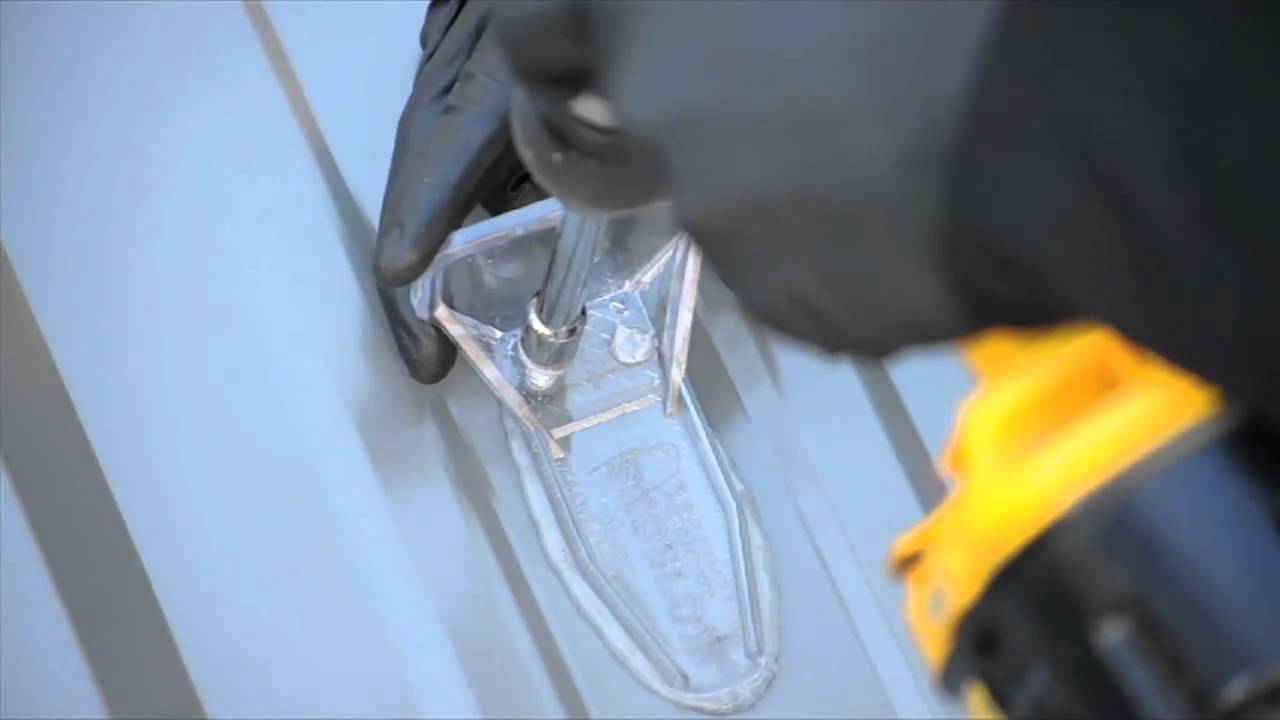
We'll begin with the adhesive attachment method. To get started, refer to your spacing layout and mark where each staggered row will be installed. We recommend using string lines to ensure that each row is straight. Next, clean the roof surface where each snow guard will be placed. Do not allow the cleaner to touch the snow guards. When the panel is fully dried, cut a wide nozzle opening in the tip of the Surebond SB-190 tube and puncture the inner seal. Generously apply the Surebond SB-190 adhesive to the entire base of the snow guard. Make sure there's an adequate squeeze out around the perimeter when the guard is firmly pressed onto the panel. When straddling a minor rib with the interchangeable base of the Snojax II or IceJax models, the entire gap must be filled in order to ensure a weather-tight seal. Place the face of the snow guard toward the ridge of the roof and press down firmly to ensure complete adhesion. Check the squeeze-out for gaps, and while wearing a rubber glove, finger wipe to fill any voids to ensure a weather-tight seal. Proceed to the next guard according to your spacing layout from SpacingTool.com. On steeper pitched roofs, use string lines to hold the snow guards in place and to prevent them from sliding until the adhesive sets up, usually in 24 hours.
The second method for installing snow guards is by mechanical attachment. Start by referring to your spacing layout. Next, clean the roof surface where each snow guard will be placed. Do not allow the cleaner to touch the snow guards. Mark where each staggered row will be installed. When the panel is fully dried, cut a wide nozzle opening in the tip of the sealant tube and puncture the inner seal. Depending on the type of screw used, some installers prefer to pre-drill starter points. Generously apply the sealant to the entire base of the snow guard. Make sure there's an adequate squeeze out around the perimeter when the guard is firmly pressed onto the panel. When straddling a minor rib with the interchangeable base of the Snojax II or Icejax models, fill the entire gap to ensure a weather-tight seal. If you are installing metal snow catcher snow guards, apply sealant generously to the bottom unless an EPDM sealer pad is already affixed to the guard. Place the face of the snow guard toward the roof ridge. Use a neoprene washer and #14 screw to penetrate through the guard and into a purlin, structural support, or at least 2-inch-thick wood blocking underneath. Tighten each screw enough to compress the neoprene washer without over-tightening or deforming the gasket. Check squeeze out for gaps, and while wearing a rubber glove, finger wipe to fill any voids to ensure a weather-tight seal. Then proceed to the next guard according to the spacing layout.
The third method of attachment used only with snow breaker snow guards is with 3m tape. Refer to the recommended spacing layout at SnowBreaker.com and mark where each row will be installed. Clean the roof surface where each snow guard will be placed. Do not allow the cleaner to touch the SnowBreaker or 3M tape. When the panel is fully dried, peel the red plastic backing from the pre-adhered 3M tape on the base of the SnowBreaker. Place the forward cutting edge toward the ridge of the roof. Press down and hold firmly for 10 seconds to ensure complete adhesion. Cut a narrow nozzle opening in the tip of the Surebond SB-190 tube and puncture the inner seal. Apply an adequate bead of adhesive around the entire base of the SnowBreaker to ensure a weather-tight seal. Proceed to the next guard according to the spacing layout. We hope this video has been informative. If you have any questions, please call us at 1-800-SNOJAX-1 or visit us at Snojax.com.
Thank you for using SnoBlox-Snojax snow guards.
Snow Rail Installation Video:
Product Installation Instructions:
Please refer to the Spacing Guidelines Pages for proper snow guard placement. Always consult and architect or engineer for exact spacing recommendations for your project.
These installation guidelines are provided as assistance to installers with commercial and residential sites. www.SnoBlox-Snojax.com takes no responsibility for errors or omissions and cannot be held responsible for product installation.
Snow Guards
Standing Seam Snow Rails
Screw-Down Snow Rails
SataMount™
SnoCleat RC
SnoCleat RCT
VentSaver HD
VentSaver EZ
View and Print
VentSaver SS Plates
View and Print
VentSaver SD Plates
View and Print
SnoCleat PBR
View and Print
SnoCleat 2.67
Warranty:
The following warranty is made in lieu of all other warranties expressed or implied. Recommendations for proper use of the product are based on tests believed to be reliable. Any goods proven to be defective due to materials will be replaced, or the purchase price refunded, but in no event shall the manufacturer be responsible for damages in excess of the purchase price. The user shall determine the suitability of the product for its intended use and assumes all risks of its use or handling.
SnoJax II, Deuce, Ace, EcoBlox, IceJax I, Icejax II, and SnowBreaker installation instructions using SureBond SB-190 clear adhesive. SureBond SB-190 requires 28 full days (672 accumulative hours) of temperatures of 50° Fahrenheit or above to achieve a full cure.
SureBond SB-190 is NOT recommended on copper, lead-coated copper, or screw-mounted applications.

1. Clean the roof surface where the guard will be placed with Xylene (Xylol), isopropyl alcohol, or panel wipes. Do not allow the cleaner to come in contact with the plastic.
2. Allow the panel to dry fully. Cut the tip, puncture the inner seal, and generously apply adhesive to the entire base of the guard to provide an adequate squeeze-out around the perimeter when the snow guard is pressed firmly on the panel. When straddling a minor rib with Snojax II or Icejax, fill the gap to ensure a weather-tight seal.
3. Place the face of the snow guard toward the roof ridge and press firmly to ensure complete adhesion. Finger-wipe the entire perimeter to fill any gaps.
TIP BOX
• The SnoJax I should not be adhesive mounted.
• Allow 50° F or above for 28 days for full cure.
• Secure a string line to prevent snow guards from sliding on steep-pitched roofs while the adhesive sets up for 24 hours.
SnoJax I, Snojax II, Deuce, Ace, EcoBlox, IceJax I, IceJax II, SnowCatcher, and SnowBreaker installation instructions using #14 screws with neoprene washers and silicone. A Non-Acetic neutral curing sealant must be used on bare galvanized or galvalume roofs.
Screw through the guard into a purlin, structural support or at least 2” thick wood blocking.

1. Clean the roof surface where the guard will be placed with Xylene (Xylol) or isopropyl alcohol. Do not allow the cleaner to come in contact with the plastic.
2. Generously apply the silicone to the entire base to provide an adequate squeeze-out around the entire perimeter when the snow guard is fastened firmly on the panel.
When straddling a minor rib with Snojax II or IceJax, fill the gap to ensure a weather-tight seal.
If using the SnowCatcher with an EPDM sealer: Do not apply silicone to the base, only apply a bead of silicone around the perimeter to form a weather-tight seal.
3. Place the face of the snowguard toward the roof ridge. Use neoprene washer equipped #14 screws to screw through the guard into a purlin, structural support, or at least a 2” thick wood blocking underneath. Tighten each screw enough to compress the neoprene without over-tightening. Finger wipe the perimeter to fill any gaps.
TIP BOX
• Surebond SB-190 is not recommended as a sealant when screw mounting the guards.
• Some users prefer to pre-drill starter points.
• We do not recommend the screw-down method on floating standing seam roof panels.
Instructions for peel and stick installation of SnowBreaker snow guards using 3M tape and SureBond SB-190 clear adhesive.
After installing SnowBreaker snow guards, apply a bead of SureBond SB-190 around the entire perimeter to form a weather-tight seal.
3M tape requires temperatures of 35° Fahrenheit or above for 24 hours to achieve full cure.

1. Clean the roof surface where the guard will be placed with Xylene (Xylol) or isopropyl alcohol. Do not allow the cleaner to come in contact with the plastic.
2. Allow the panel to dry fully. If the 3M tape is not adhered to the SnowBreaker remove the white backing from one piece of tape. Align the tape with the guard and press firmly, avoiding bubbles and creases in the tape. Peel the red plastic backing from the base of the SnowBreaker.
3. Place the arrows and cutting edge facing uphill. Press and hold firmly for 10 seconds. Apply SureBond SB-190 around the perimeter. Finger wipe to form a weather-tight seal.
TIP BOX
• SnowBreaker can be installed year-round because of short temperature requirements.
• Always place the cutting edge facing uphill.
• 3M tape is only recommended for the SnowBreaker snow guard model.
SlateGuard Installation Instructions. SlateGuard attaches to pre-existing roof nails or slate nails so always verify SlateGuard is compatible with your shingle or slate attachment.

1. Slightly lift panel or slate to slide SlateGuard beneath to locate and engage nail with slot. Pull firmly to set.
TIP BOX
• When installing on a slate roof, use a ripper to locate nails and to loosen slate tile slightly.
Before Installing the
SnoBar/ColorBar Bar System Never use the SnoBar/ColorBar system as a tie off point. Repeat these 6 steps for each full section of bar
until the row is completed. Action Manufacturing, LLC and/or IceBlox, Inc. are not
responsible if failure occurs from improper installation,
set screw torque, panel attachment, roof system
installation, or inadequate design layout. Be sure to read and follow all instructions. Please call
800-766-5291 if you have any installation questions. It is the sole responsibility of the Designer/Architect, Installer,
or Owner to assess the suitability of using the SnoBar or
ColorBar systems based on the above design considerations.
Read the DESIGN CONSIDERATIONS starting on page 8.
Always make sure the roof panels are properly attached
to the structure at a fixed point.
NOTE:
Standing Seam Roof Clips normally DO NOT provide
a fixed point for floating roof panels. The standing seam
panels must be attached with enough fasteners to withstand
the added load incurred by retained snow. If unsure, please
consult with a professional metal roofing installer.
REQUIRED TOOLS:
Make sure to have the proper tools for installing the
SnoBar/ColorBar System.
• Hammer for tapping in end caps for SnoBar
• Drill Gun with 3/8” Nut Driver Bit for driving Tek Screws
• Torque Wrench that reads into in/lbs. (inch pounds)
• 3/16” Allen Bits for tightening set screws
• Flex Pivot Bit for Drill Gun – Helps on shorter seams.
• Tape Measure
• Hacksaw
• Deburring File
• Pencil & Sharpener
SYSTEM PARTS:
Verify quantities of the parts against the packing slip. Your system should include:
• SnoBar Clamps with Cup Tip Set Screws
• RoofClamps (optional) w/screws, top bolts and washer
• Bar
• Self-Drilling Tek Screws
• End Caps (only for SnoBar)
• Splice Connectors (only for multiple ColorBars)
• Optional Ice Stoppers (If ordered with your project).
DETERMINE LAYOUT OF ROWS:
Refer to the layout that was provided when the system was
purchased. If no layout was provided, then a basic layout
would be one row 12” up from the eave edge (or over the load
bearing wall) and all additional rows will be spaced evenly up
the slope.
For example, if the roof from eave to ridge is 26'-0”, and you
were putting on two rows, you would put the first row at 12”
up from the eave (or over the load bearing wall), and the second
row would be put at 13'6” from the eave edge (or 12'-6”
from the first bar).
Make sure all workers are properly harnessed and anchored to the roof according to
OSHA fall protection guidelines.
INSTALLATION INSTRUCTIONS:
• Never extend the bar more than 3”
past the last clamp on the end of
a row or a row terminating in a
valley.
• Bars may need cut to length depending
on the panel width. Do
not discard any cutoffs until the
job is completed.
• Short sections of SnoBar or
ColorBar must span at least two
seams. In a continuous run of
SnoBar or ColorBar, cutting of
the bar may be required to avoid
having a short section of bar at
one seam. A short bar clamped to
a single seam
1. Pre-load 2 set screws into all SnoBar clamps prior to getting
on the roof, with the cup tips pointed inward toward
the panel seam. Leave enough of a gap between the tips of
the set screws for the clamp to slide easily over the seam.
2. Based on the layout, measure approximately 12” up the
seam from the eave edge. If there is a long overhang, place
the first row over the load bearing wall. Mark with a pencil
at the farthest seam starting at the left. Then mark the
same distance from the eave on the seam just short of the
length of the bar you are installing. For example: If installing
a full 12' section of bar you would want the 2nd
mark to be just short of 12'
from the 1st mark. Be sure
the two seams are not wider
than the length of bar
that you are installing. Do
not place the clamps over
clips whenever possible to
avoid restricting the thermal
expansion of the panels.
3. Set the first SnoBar Clamp onto the furthest left seam of
the bar section at your 1st pencil mark. Hand tighten the
set screws to the seam, making sure the clamp is centered
and the bottom of clamp is pressed down tight to the top
of the seam. The (2) holes in the bar receiver section of
the SnoBar Clamp should be facing upslope when
properly mounted onto
the seam. While putting
downward pressure on the
SnoBar Clamp, torque the
2 set screws to 90 inch/
lbs. Repeat this step to
install a second SnoBar
Clamp on the furthest
right seam as marked in Step 2.
4. Place a full section of bar down
into both SnoBar Clamps (do not
attach bar to clamps yet). This
section of bar will be used as a
straight edge to install the remaining
SnoBar Clamps for that bar
section. The clamps should only
be set in place with the set screws
being hand tightened.
Once all SnoBar Clamps in the
bar section are installed, torque
all set screws to 90 inch/lbs.
While applying downward pressure
to the bar.
5. If using the 1” square SnoBar, install the supplied Plastic
End Caps at each end of the SnoBar. Be sure to de-burr
any field cut bars prior to installing End Caps. If using
the aluminum ColorBar, disregard this step.
6. The next step is to attach the bar
to the clamps. SnoBar/ColorBar
should never extend more than
3” past the last clamp at either
end of a continuous row. Starting
at the farthest left clamp,
make sure the bar is seated
tightly while applying downward
pressure. Install the (2)
Tek Screws through the back of
the SnoBar Clamp into the bar
using the 3/8" driver bit. Follow
the same procedures for each
clamp while applying downward
pressure as you progress down the section of bar.
7. When the optional IceStoppers are installed, the short leg
of the IceStopper should be facing upslope with the Tek
screw holes lining up with the upslope side of the bar. If
installing one IceStopper per panel, then center between
clamps. Hold tightly to the upslope side of the bar and install
(2) Tek Screws while applying downward pressure.
On panels 18” or wider, use two or three IceStoppers
spaced equally between panel seams.
If you did not order IceStoppers with your system and you
experience snow and ice sliding under the bars, they can
easily be added in the future.
8. For SnoBar, butt joints
should always be centered
in the panel valley with no
more than a 2” gap between
butted ends. Some
panels require the bars to
be cut to obtain correct
seam spacing.
For ColorBar, the supplied
Splice Connectors
create a continuous run of
bar therefore the bar ends
should be no further than
1/8” apart. ColorBar butt
joint connections can be
made anywhere along the
row other than inside the clamp, as long as splice connectors
are properly installed with 1 Tek screw each.
9. Space additional rows of SnoBar or ColorBar evenly up
the slope, always measuring from the eave according to
the layout provided. This gives the best protection against
snow and ice slides while providing balanced structural
loading across the entire roof structure. If not sure how to
space additional rows, please call us at 800-766-5291.
For example, if you have a 33 foot panel length from eave
to the ridge that requires three rows of SnoBar or Color-
Bar, place the first row 12” up from the eave, the second
row 11’ from the eave, then place the third and final row
22’ up from the eave.
DESIGN CONSIDERATIONS:
1. All loads incurred by the SnoBar/ColorBar System will be
transferred to the panels. Therefore, proper panel attachment
to substrate/structure is necessary to prevent roof
panels from sliding under snow load. New and existing
structures must be evaluated to insure they can withstand
retained snow loads. (In instances where there is an overhang
at the eave edge, it is imperative to make sure that
the overhang can hold the accumulated snow load, otherwise,
the first row of SnoBar or ColorBar should occur at
the load bearing wall.)
2. It is not recommended to place the SnoBar/ColorBar System
in isolated areas such as over doorways, vents and partial
roof areas. Please call for special design considerations
in these areas.
3. No snow retention system is capable of retaining 100% of
snow and ice from falling off the roof. The system is only
designed to mitigate the dangers of sliding snow and ice.
4. Roof systems should be a minimum of 24 gauge steel and
have a seam height of at least 1 inch. Do not use the
SnoBar/ColorBar system on seams with separate seam
covers or batten strips.
5. Clamp spacing varies depending on seam spacing (12”o.c.
up to 42”o.c.). Clamps should be placed on every seam,
so that the load is distributed evenly to every roof panel.
Yes, we know that other manufacturers may only provide
a clamp for every other seam in order to be the lowest
priced, but this is very risky and usually not warrantied
against failure. We design systems that last the life of the
roof and back them up with a Lifetime Warranty against
failure.
6. The Designer/Architect, Installer, or Owner of the project
should have knowledge of the local snow loads (ground
snow load PSF/kPa), climatic conditions, roof slope, roof
orientation, potential drifting, and roof design prior to installing
a SnoBar or ColorBar system.
7. System layout is calculated using length of panels,
Ground Snow Load, roof slope, and roof areas needing
protection from falling snow and ice. More than one row
of SnoBar/ColorBar may be needed. We provide free design
service to make sure it gets done correctly the first
time. Call customer service at 800-766-5291 or email
support@snojax.com with any questions.
8. Finally, no matter how well a system is designed, Mother
Nature may create unforeseen conditions that may have not
been considered, such as drifting, ice, uncharacteristic
amounts of snowfall, etc. Owners must be aware of these
conditions and when these extremes are reached, snow and
ice should be physically removed from the roof. Snow retention
systems do not prevent snow drifting on overhangs or
cornices. The owner must be aware of these situations and
remove them as they occur.
Before Installing the
SnoBar/ColorBar ColorBracket System Never use the SnoBar/ColorBar system as a tie off point. Action Manufacturing, LLC and/or IceBlox, Inc. are not
responsible if failure occurs from improper installation,
set screw torque, panel attachment, roof system
installation, or inadequate design layout. Be sure to read and follow all instructions. Please call
800-766-5291 if you have any installation questions. It is the sole responsibility of the Designer/Architect, Installer,
or Owner to assess the suitability of using the SnoBar or
ColorBar systems are based on the above design considerations.
Read the DESIGN CONSIDERATIONS on the last page.
NOTE:
ColorBrackets can be used with either SnoBar or ColorBar.
The 2.67 ColorBrackets are to be used on wavy 2.67 corrugated metal panels and the Tall/Short ColorBrackets are to
be used on all other mechanically fastened metal R-Panels.
REQUIRED TOOLS:
Make sure to have the proper tools for installing the
SnoBar/ColorBar System.
• Rubber Mallet for inserting end caps into SnoBar
• Drill Gun
• 3/8” Nut Driver Bit for driving 1.5” Master-Driller Tek
Screws into steel purlins.
• 5/16” Nut Driver Bit if using 2” Wood Screws for the
Tall/Short ColorBracket or 3” Wood Screws for 2.67
Corrugated ColorBracket mounted into wood purlins.
• Tape Measure
• Hacksaw
• Deburring File
• Pencil & Sharpener
SYSTEM PARTS:
Verify quantities of the parts against the packing slip. Your system should include:
• ColorBracket Mounts with Foam Gaskets
• SnoBar or ColorBar
• Self-Drilling Tek Screws
• (3) Self Drilling Screws Per Tall/Short ColorBracket or
• (4) Self Drilling Screws Per 2.67 ColorBracket
• End Caps (only for SnoBar)
• Splice Connectors (only for ColorBar)
INSTALLATION TIPS:
• Never extend the bar more than 3” past the last bracket on
the end of a row or a row terminating in a valley.
• Bars may have to be cut to length depending on the panel
width. Do not discard any cutoffs until the job is complete
Short sections of SnoBar or ColorBar must span at least two
seams. In a continuous run of SnoBar or ColorBar, cutting of
the bar may be required to avoid having a short bar at one
seam.
DETERMINE LAYOUT OF ROWS:
Refer to the layout that was provided when the system was
purchased. If no layout was provided, then a preliminary
basic layout would be one row 12” up from the eave (or over
the load-bearing wall) and all additional rows spaced evenly
up the slope. Always follow the manufacturer’s project-specific design recommendations to validate the warranty.
Make sure all workers are properly harnessed and anchored to the roof according to
OSHA fall protection guidelines.
INSTALLATION INSTRUCTIONS:
1. Based on the layout, measure 12” to 18” up the panel
from the eave (if there is an overhang, place the first row
over the load-bearing wall). Mark with a pencil at the
farthest panel valley starting at the left. Then mark the
same distance from the eave on the next panel valley just
short of the length of the bar you are installing. For example: If installing a 6' section of bar you would want
the 2nd mark to be just short of 6' from the 1st mark.
2. Apply foam gasket and set the
first ColorBracket onto the furthest left seam of the bar section
at your 1st pencil mark.
The (6)
holes in the Tall/Short ColorBracket should be facing upslope
using 3 screws in an s-pattern.
The 2.67 ColorBracket, requires
(4) 3” Screws mounted on top of
the ribs in a square pattern using
the outside holes. Make sure that each screw is fully embedded into the structural material below. Repeat this
step to install a second ColorBracket on the furthest right
seam as marked in Step 1.
3. Place a full section of the bar down
into both ColorBrackets (do not
attach the bar to ColorBrackets yet).
This section of the bar will be used as
a straight edge to install the remaining ColorBrackets for that
bar section.
4. If using the 1” square SnoBar, install the supplied Plastic
End Caps at each end of the SnoBar. Be sure to de-burr
any field cut bars prior to installing End Caps. If using the
aluminum ColorBar, disregard this step.
5. The next step is to attach the
bar to the ColorBrackets.
SnoBar/ColorBar should never
extend more than 3” past the
last ColorBracket at either end
of a continuous row. Starting
at the farthest left ColorBrackets, make sure the bar is seated
tightly, while applying downward pressure. Install the (2)
Tek Screws through the back
of the ColorBrackets into the
bar using the 3/8" driver bit.
Follow the same procedures
for each ColorBracket, apply downward pressure, as you
progress down the section of
bar.
6. For SnoBar, Butt
joints should always
be centered in the
panel valley with no
more than a 2” gap
between butted ends.
Some panels require
the bars to be cut to
obtain correct seam
spacing.
For ColorBar, The supplied Splice Connectors create
a continuous run of bar therefore the bar ends should
be no further than 1/8” apart. ColorBar butt joint connections can be made anywhere along the row other
than inside the Tall/
Short ColorBrackets,
as long as splice connectors are properly
installed with 1 Tek
screw each.
2” ColorStrips can be made
from excess metal
panels on the job site.
User-supplied ColorStrips can be installed on the face of the ColorBar and
in the front slot of the Tall/Short ColorBracket.
7. Space additional rows of SnoBar or ColorBar evenly up
the slope, always measuring from the eave according to
the layout provided. This gives the best protection against
snow and ice slides while providing balanced structural
loading across the entire roof structure. If you are unsure
how to space additional rows, please call us at 800-766-
5291.
For example, if you have a 31'-6” panel length from eave
to the ridge that requires three rows of SnoBar or ColorBar, place the first row 18” up from the eave, the second
row 11’6” from the eave, then place the third and final
row 21'-6” up from the eave.
DESIGN CONSIDERATIONS:
1. New and existing structures must be evaluated to ensure
they can withstand retained snow loads. (In instances
where there is an overhang at the eave edge, it is imperative to make sure that the overhang can hold the accumulated snow load, otherwise, the first row of SnoBar or
ColorBar should occur at the bearing wall.)
2. It is not recommended to place the SnoBar/ColorBar System in isolated areas such as over doorways, vents and
partial roof areas. Please call for special design considerations in these areas.
3. No snow retention system is capable of retaining 100% of
snow and ice from falling off of the roof. The system is
designed to mitigate the dangers of sliding snow and ice.
4. Designer/Architect, Installer, or Owner of the project
should have knowledge of the local snow loads (ground
snow load PSF/kPa), climatic conditions, roof slope, roof
orientation, potential drifting, and roof design prior to installing a SnoBar or ColorBar system.
5. System layout is calculated using the length of panels,
Ground Snow Load, roof slope, snow loading, and areas
needing protection from falling snow. More than one row
of SnoBar/ColorBar may be needed. We provide free design service to make sure it is done correctly the first time.
Please give us a call at 800-766-5291 or send an email to
support@snojax.com with any questions.
6. Finally, no matter how well a system is designed, Mother
Nature may create unforeseen conditions that may have
not been considered, such as drifting, ice, uncharacteristic
amounts of snowfall, etc. Owners must be aware of these
conditions and when these extremes are reached, snow
and ice should be physically removed from the roof. Snow
retention systems do not prevent snow drifting on overhangs or cornices. The owner must be aware of these situations and remove them as they occur.
What’s Included:
• (2) 27” SataMount Rails - Unistrut Defender Series Steel 100+ year service life finish, 12 ga. 1-5/8”
• (4) ¼-20 Channel Nuts - Defender Series Finish
• (4) ¼-20x1.5” Bolts - 304 Stainless Steel
• (4) ¼” stainless steel flat washers
• (4) Black Vinyl End Caps
• (4) RCT Clamps with 3 set screws and 1 top bolt and washer each.
Tools Needed
• Screw gun with 3/16” Allen bit, flexible bit extension is helpful for shorter seams.
• Ratchet with 9/16” socket
• Pencil and tape measure
• Micro torque wrench (that reads in/lbs.) with 3/16” Allen bit.
• Appropriate Fall Protection
SataMount Instructions
1. Pre-Assemble the SataMount along with your satellite mounting base before you get on the roof.
• Position the two SataMount Rails parallel to each other and a few inches apart, with the open side of the SataMount Rails facing upwards. (Be sure to center the satellite mounting base onto the SataMount rails so the load is equally dispersed across the four RCT clamps once the assembly is installed.)
• Set the satellite mounting base on top of the SataMount Rails and pencil mark the location of the mounting holes. Insert a ¼” channel nut into the rail and position at the bolt locations you just marked for your mounting base.
• The nuts should be positioned so the spring (if included) is down and the nut portion with the 2 groves is facing to receive the mounting bolt in the next step. (Note: The springs are designed to hold the nut in place until the bolt begins to thread into the nut. The springs will sometimes fall off or get lost, however, the nuts can still be used by holding them in place until the bolt threads are engaged into the nut.) Use the ¼” mounting hardware to securely fasten your satellite mounting base to each SataMount Rail. (The four included mounting bolts are sized for the most common applications. If your mounting base required a different length bolt, be sure to source new bolts with ¼-20 threads in a non-corrosive finish such as stainless steel.)
• Measure the on-center spacing of your roof seams to determine the mounting width of the four RCT clamps and pencil mark that width onto the SataMount Rails. Attach two RCT clamps to each SataMount Rail, one at each end located at the pencil marks, and use the top bolt to hold it in loosely in place. In certain instances, it may be necessary to drill additional 5/16” holes in the SataMount Rail to properly space the RCT clamps for your seam spacing. Don’t fully tighten the RCT top bolts yet. Now is a good time to back each of the 3 RCT set screws out until the screw tips are flush with the inner wall of the clamp.
2. Ascend the roof with your fully assembled SataMount and satellite base. Locate the most appropriate installation location for the assembly. Important - The SataMount and satellite dishes are not designed to withstand snow loads. The SataMount assembly should be mounted within 3’ of the peak of the roof OR protected by a snow retention system mounted upslope.
3. Set the assembly across the two seams you will be mounting to. The clamps should be as close to centered onto each seam as possible and the SataMount rails should be running horizontally across at least two seams. Use a pencil to mark the location of the four RCT clamps.
4. Set the assembly aside and remove the four RCT clamps and top bolts from the assembly. Install the four RCT clamps onto the seams at your pencil marks. Apply downward pressure as you torque all 12 set screws to 90 in/lbs. (only 7.5 ft/lbs.) using a 3/16” Allen bit.
5. Center the SataMount assembly on top of the four RCT clamps. Insert and tighten all RCT top bolts to 90 in/lbs. (only 7.5 ft/lbs.).
Mount VentSaver HD In 5 Easy Steps:
NOTE:
Optional Wing Diverters do not work on every application and/or may need to be modified on-site.
REQUIRED TOOLS:
Make sure to have the proper tools for installing the
VentSaver HD.
• Cordless Drill with 5/16" driver
• Tin snipes
• Two 7/16" wrenches
• Caulk gun.
INSTALLATION INSTRUCTIONS:
1. Attach FIN to BASE ANGLE - Assemble with three 1/4" x 3/4" s.s. bolts. NOTE: In case of rib obstruction, the base angle is reversible.
2. BASE Installation - Put sealant on bottom of base angle. Place cable over chimney or vent with VentSaver centered behind and close to pipe. Fasten the base to the roof with the six 2" lag screws.
3. STRAP Installation - Pull on cable end with pliers until snug. Keep the shoulder strap on the opposite side of the pipe from the VentSaver. Tighten the nut and bolt firmly. Trim excess cable.
4. DIVERTER WING KIT Installation - Install the Snow Diverter Wing Kit using the provided spacers, where necessary, to compensate for minor rib height.
5. Double-check ALL fasteners for tightness!
Mount VentSaver EZ In 3 Easy Steps:
REQUIRED TOOLS:
Make sure to have the proper tools for installing the
VentSaver HD.
• Cordless Drill with 5/16" driver
• Tin snipes
• Two 7/16" wrenches
• Caulk gun.
INSTALLATION INSTRUCTIONS:
1. Attach FIN to BASE ANGLE - Assemble with three 1/4" x 3/4" s.s. bolts. NOTE: In case of rib obstruction, the base angle is reversible.
2. BASE Installation - Put sealant on bottom of base angle. Fasten base to roof with the six 2" #14 Roof screws with neoprene washers and 100% silicone at the base. (Some roofs may require longer screws)
3. STRAP Installation - Thread cable around the pipe or vent and cross both ends back through the hole at the top of the base fin. Pull tightly on both ends to create a snug hold before tightening the bolts on the provided U-clamps on either side of the fin. Cut off the excess cable. For PVC vent pipes, it is recommended to cut off 2" to 3" above the VentSaver. NOTE: For smaller applications, the stainless steel shoulder strap on the cable is not necessary
4. Double-check ALL fasteners for tightness!
The VentSaver Mounting Plate Kit is an add-on product that allows the VentSaver, with or without optional the Wing Kit and Height Extender, to be mounted on most standing seam roof panels without panel penetration. *NEVER use the VentSaver Mounting Plate
as a roof anchor tie-off point. Screws must be fastened into the decking or structural support below.
This plate can also be used on screw down roof panels, when the height extender and/or wing kit is required. Please note: The Height Extender can only be used with the optional Wing Kit. The VentSaver Mounting Plate is a necessary option on some screw down panels where modification of wing kit is not desirable.
REQUIRED TOOLS:
Make sure to have the proper tools for installing the
VentSaver HD.
• Safety Goggles, Gloves and Fall Protection
• Caulk Gun
• Tape Measure
• Pencil or Sharpie to mark clamp and base mounting bracket holes
• Ratcheting Torque Wrench (capable of reading “inch” in/lbs.)
• Cordless Impact Driver with Socket Adapter
• Socket Wrench to fit Socket Sizes Below
• 9/16” Socket for RoofClamps
• 7/16” Socket & 7/16” Wrench to Attach
• 3/8” Socket for Tek Screws
• 5/16” Socket for Cable Clamps
• Cordless Drill
• 1/4” Drill Bit (For SD VentSaver Plate, Fin and Height Extender holes)
• 1/8” Drill Bit (For Drilling Tek Screw Starter Holes in Plate)
• Hacksaw or Chop Saw with Metal Blade
CHOOSING THE VENTSAVER PLATE ATTACHMENT METHOD
Standing Seam Roofs: that can not accept screw fasteners, require the SS (Standing Seam) VentSaver Mounting Plate with included roof clamps. Please verify that the roof clamps will fit your seam before ordering.
Screw Down Roofs: When the location of the pipe or chimney makes it difficult to mount the VentSaver base, use the SD (Screw Down) Mounting Plate. The SD VentSaver Plate kit may also be considered to avoid modifying the optional wing kit. The Optional Wing Kit is required when using the C-Kit Height Extender. Please verify that you have adequate mounting material underneath of the roof to attach the plate. Never attach the plate to just the metal roof panel. It is the responsibility of the installer to fasten the SD VentSaver Mounting Plate into a solid substrate “below the panel” that is adequate enough to support the mounting requirements of the plate. There must be a minimum of 12 screws installed through the plate, into the substrate or decking below. The installer must verify and confirm that the screws are the correct length and type.
*Make sure all workers are properly harnessed and anchored to the roof according to OSHA fall protection guidelines.
VentSaver Plate Kit Contents
The SS (Standing Seam) VentSaver Plate Kit Includes:
(1) 1/4” Adjustable Aluminum Plate – 27” wide
(1) 1/8” Aluminum Ice Ramp w/ edging strip
( 4) RCT Universal fit standing seam clamps
(12) Tek screws – 1/4” x 1” 3/8” hex head
(12) Set screws for the clamps – 3/16” hex/allen drive
(4) 9/16” Hex RCT top bolts with stainless washers
(1) 3/16” Hex bit for set screw tightening
The SD (Screw Down) VentSaver Plate Kit Includes:
(1) 1/4” Adjustable Aluminum Plate – 27” wide
(1) 1/8” Aluminum Ice Ramp w/ edging strip
(12) 3 Inch 1/4-14 Wood Screws w/Neoprene Washers
(1) Tube of NovaFlex All Weather Silicone
(12) Tek screws – 1/4” x 1” 3/8” hex head
ATTACH SS (Standing Seam) PLATE to ROOF PANEL
1. The 12” VentSaver base bracket has 6 holes on the horizontal base and 4 holes where it attaches to the fin vertically. Determine which holes will line up best with your application. Take the mounting bracket placement into consideration, if using the optional Wing Kit and/or C-Kit before attachment. Do not attach the base mounting bracket to the VentSaver plate yet.
2. With the fin now attached to the base bracket, set the VentSaver base bracket onto the Aluminum Plate with the 6 holes facing down. Align the entire assembly in front of the pipe. Move the Plate until the fin is just touching the pipe. Mark the (6) holes of the Base Angle and mark the location of the 4 RCT clamps on the seams.
3. Attach the 4 RoofClamps onto the roof panel using the marks made from the previous step. Hand tighten the 3 RoofClamp cup tip set screws. Loosely attach the plate with the top bolts and washers. Once the exact locations of the clamps are confirmed, remove the 4 top bolts and plate. Torque the RoofClamp set screws to 90 inch pounds. Do not attach VentSaver Base Bracket until after installing the Ice Ramp.
ATTACHING SD (Screw Down) PLATE TO ROOF PANEL
Set plate on high seams just upslope of the pipe or chimney to be protected. Adjust the plate from side to side so that it sits on at least three seams. It does NOT matter if the vent pipe or chimney does not end up centered in the middle of the plate. Mark the seams of the roof panel, where the plate will be mounted, and mark where the 12 holes will be drilled in the plate. Remove the plate from the panel and drill (12) 1/4” holes in the plate. There should be 4 evenly spaced holes in the plate for each seam. Before drilling the holes, make a mark where the VentSaver Base Bracket and Wing Kit will be mounted on the plate as shown in step 1 & 2 on the previous page. Before setting the plate back down on the panel, generously apply the included silicone on the high seams between the marks previously made. Set plate down on panel in the bed of silicone and screw the plate down. The screws are self tapping and should self drill through the panel.
This Step is Essential for the SD and SS VentSaver Plate!
The Ice Ramp installation is vital to keep ice from sliding under the Adjustable Aluminum Plate and damaging the base of the pipe and/or the boot. Custom cut into as many pieces as it takes to keep the snow and ice from going under the plate. A Sawzall with a metal blade, handheld angle grinder a with cutoff blade, chop saw, or even a simple hacksaw can be used. Take precautions by using gloves and safety goggles to protect yourself from injury while cutting and installing the Ice Ramp. Slide the rubber edging strip on the custom cut ramp pieces before screwing to the ramp to the plate. To avoid notching out the ramp, attach ramp before attaching VentSaver mounting bracket to plate.
Install VentSaver to Aluminum Plate
1. Skip this step if installing the optional Height Extender C-Kit. Set the base bracket with previously assembled fin on installed plate. Run the cable thru the large hole in the top of the fin, around the pipe and back through the hole. Install a cable lock on either side of the fin as shown, being sure to lock both cables in each cable lock. Vice grips can be used to hold the cable together while you install the cable locks using 5/16” socket and screw gun. Trim off or tuck in the excess cable.
2. With the base mounting bracket in place, predrill one 1/8” starter hole into the plate through the middle hole of the base bracket. Make sure the bracket is straight and predrill each of the 5 remaining holes, with the 1/8” drill bit and install the base mounting bracket with the remaining 5 Tek screws.
Installing “Optional” VentSaver Wing Kit to Aluminum Plate
1. The wing kit is an optional accessory designed to add extra protection for the pipe. It is also a crucial component when adding the Height Extension C-Kit. Fasten the wings to the fin with the 2 longer bolts and nylon lock nuts. Predrill six 1/8” starter holes in the plate and install the 6 Tek screws.
Installing “Optional” VentSaver Height Extender C-Kit
1. Remove cable if previously installed. Install upper and lower cable in the upper and lower predrilled holes of the Height Extender C-Kit
2. If the wing kit is in the way, move the fin back 1 hole on the mounting bracket. Predrill 1/4” holes in VentSaver fin after installing cables and confirming placement of C-Kit Height Extender.
3. Install nylon lock nut and washer through the holes and tighten with 7/16 socket and wrench.
VentSaver Xtreme with Upper Wings For Direct Mount to Screw Down Metal Roofs
Please read and fully understand all warnings,
instructions and regulations prior to use.
REQUIRED TOOLS:
Make sure to have the proper tools for installing the
VentSaver Xtreme.
• Drill with 7/16" socket
• 7/16" wrench
• Squeeze Clamp
• 8mm socket for roofing screw installation
• 1/4” drill bit
• 12” level
MOUNTING HARDWARE REQUIRED:
• 20 roofing screws
• 11- 1” bolts with lock nuts
• 4 cable locks
• 2 cables
• 6-8 spacers
DIMENSIONS ON A 4:12 PITCH ROOF:
• Lower Wingspan 21.5”
• Upper Wingspan 12”
• Fin Height 14.5”
• Height with Upper Wing Kit 32”
INSTALLATION INSTRUCTIONS:
1. Assemble the two upper wings together with two 1” bolts and lock nuts inserted thru the two pre-drilled holes on the 3” flange.
Use 7/16” socket/wrench to tighten. Place an 8” wood block on the up-slope side of the pipe. Place the assembly on top of the temporary wood block so the 3” flange is pointing up-slope, and the V-shaped side is straddling the pipe.
2. Each side of the upper wing has a pre-drilled hole in the top and bottom corner. Slide the cable spacer plate into the center of each steel cable. Now insert each end of one cable into the right and left holes in the upper wings for the upper cable and repeat for the lower cable.
3. From the up-slope side of the pipe, insert both ends of the upper cable thru the upper pre-drilled hole in upper wing kit. Use a cable lock on each side of the 3” flange to lock the cable firmly around the pipe. Repeat for the lower cable.
4. Assemble the riser fin to the two mounting bases. The bases can be attached with the fin sandwiched between them or to one side depending on the panel profile you have. The goal is to have the fin as close to the center-line of the pipe as possible but will need to be mounted to a smooth flat surface. Use three 1” bolts with lock nuts in the pre-drilled holes.
5. Place the assembled fin/base up-slope of the pipe with the fin overlapping the 3” flange of the upper wing kit. The upper wing assembly can be adjusted up or down depending the roof pitch so the top of the fin overlaps the bottom of the upper wing flange and allows space for three bolts to be inserted in the next steps. Temporarily clamp in place.
6. Use twelve 2” heavy duty roofing screws to secure both mounting bases to the roof. Be sure each screw is fully embedded into structural wood for maximum pullout strength.
7. Check the upper wing kit to be sure it is plumb. Mark and drill using a sharp 1/4” drill bit through all three layers of aluminum. Insert a 1” bolt and lock nut and tighten. Repeat and drill two more evenly spaced holes and use two more bolts and nuts to fully secure the fin to the upper wing kit. Tighten all nuts. Remove the temporary wood block.
8. Lower wing kit consists of a right and left plate. The flanges with 3 holes go up against the fin and the flanges with 4 holes go down across the panel/high rib. If the wings don’t line up with the pre-drilled holes on the lower edge of the fin, you will be drilling new holes for a custom fit. You want the down-slope side of the lower wings to be close to the pipe boot so there isn’t a large gap for snow and ice to accumulate.
9. With one of the lower wings held against the riser fin, use a 1/4” drill bit thru the center factory hole in the wing to drill thru the riser fin. Be sure the wing is in the correct position on the panel before drilling. Once drilled, insert a 1” bolt thru the wing, fin and then thru the opposite wing and secure all three pieces together with a lock nut. Repeat for the other two lower wing mounting bolts.
10. Each of the lower wing flanges requires 4 fasteners. If they cross over a high rib, you will pre-drill a 1/4” hole in the flange so the roofing screw with penetrate the center of the high rib. The other holes will be fastened with screws and spacers filled with silicone or roofing sealant.
LeafBlox Installation Instructions. To clean LeafBlox simply remove the LeafBlox brushes, shake thoroughly and return to gutter.

1. Fill gutters end-to-end with LeafBlox. Slide beneath gutter nails or hangers.
2. Simply bend LeafBlox to easily fit around a corner. At the end of the gutter simply fold over the remaining portion of LeafBlox.
TIP BOX
• The black UV-treated polypropylene bristles absorb heat on sunny days which will speed up the snow and ice melting process along the gutter.
• No tools required for installation.
RoofClampTM RC and RoofClampTM RCT Installation Instructions. Use a Torque Wrench to tighten set screws to 90-inch pounds.

1. Position RoofClampTM, finger tighten set screws. Do not attach to roof clips.
2. Apply downward pressure and then tighten set screws to 90-inch pounds with a torque wrench, beginning with a single set screw.
3. Attach roof accessories to the top mounting screw. Tighten adequately.
TIP BOX
• Verify with the panel manufacturer for the recommended torque settings for the seam.
• Check all bolts and screws for fastness.
Before Installing the
SnoCleat Snow Guard System Never use the SnoCleat product as a tie off point! Important: Always install guards on complete roof sections, never isolate areas of snow guards. Action Manufacturing, LLC and/or IceBlox, Inc. are not
responsible if failure occurs from improper installation,
set screw torque, panel attachment, roof system
installation, or inadequate design layout. Be sure to read and follow all instructions. Please call
800-766-5291 if you have any installation questions. It is the sole responsibility of the Designer/Architect, Installer,
or Owner to assess the suitability of using the SnoCleat systems based on the above design considerations.
Read the DESIGN CONSIDERATIONS starting on page 8.
Always make sure the roof panels are properly attached
to the structure at a fixed point.
NOTE:
Standing Seam Roof Clips normally DO NOT provide
a fixed point for floating roof panels. The standing seam
panels must be attached with enough fasteners to withstand
the added load incurred by retained snow. If unsure, please
consult with a professional metal roofing installer.
REQUIRED TOOLS:
Make sure to have the proper tools for installing the
SnoCleat.
• Drill Gun with 3/8” Nut Driver Bit for driving Tek Screws
• Torque Wrench that reads into in/lbs. (inch pounds) for setting set screw torque to 90 in/lbs.
• 3/16” Allen Bits for tightening set screws
• Tape Measure
• Carpenter Pencil & Sharpener
SYSTEM PARTS:
Verify quantities of the parts against the packing slip. Each SnoCleat Seam Mounted snow guard should include:
• SnoCleat Roof Clamp with 3 Cup Tipped Set Screws
• RCB-2 Swivel Bracket with Top Mount Bolt & Washer
• SnoCleat with 2 Self-Drilling Tek Screws
DETERMINE LAYOUT OF ROWS:
Refer to the layout that was provided when the system was purchased. If no layout was provided, then a basic layout would be one staggered row 12” up from the eave (or over the load bearing wall) and all additional rows will be spaced evenly up the slope.
For example, if the roof from eave to ridge is 26'-0”, and you were putting on two rows, you would put the first row at 12” up from the eave (or over the load bearing wall), and the second row would be put at 13'6” from the eave (or 12'-6” from the first bar).
Make sure all workers are properly harnessed
and anchored to the roof according to
OSHA fall protection guidelines.
INSTALLATION INSTRUCTIONS:
Special Disclaimer for Seam Mounted Snow Guards:
Since there is no release factor on individual standing seam mounted snow guards, panel damage may occur in the event of a sudden snow slide. This can be mitigated by adjusting the torque setting on the top mounted bolt. The most effective method of retaining snow and ice on a metal roof is to follow the manufacturer’s layout before installing this or any snow guard system. Multiple rows of snow guards may be required.
1. Pre-load 3 set screws into all SnoCleat roof clamps prior to getting on the roof, with the cupped tips pointed inward toward the panel seam. Leave enough of a gap between the tips of the set screws for the clamp to slide easily over the seam.
2. Based on the layout, measure approximately 12” up the seam from the eave and make a pencil mark every other seam, skipping a seam. If there is a long overhang, place the first row over the load bearing wall. Do not place the clamps over clips whenever possible to avoid restricting the thermal expansion of the panels. Moving over to the skipped seams, make a pencil mark 12” above the first row that was marked on the alternating seams. There will be a SnoCleat placed on every seam but staggered across the roof. See sample layout as illustrated in below picture.
3. Set the first SnoCleat Clamp onto the seam at your 1st pencil mark. Hand tighten the set screws to the seam, making sure the clamp is centered and the bottom of clamp is down tight to the top of the seam. While putting downward pressure on the SnoCleat clamp, torque the set screws to 90 inch/lbs. Do not overtighten or use an impact gun on set screws. Repeat this step to install each row of SnoCleat Clamps on alternating seams. Every seam must have at least 1 SnoCleat and the pattern(s) must be staggered. Never install the SnoCleat in straight rows.
Install the RCB-2 Swivel Bracket with top mounted bolt and washer on top of the SnoCleat Roof Clamp and torque to 100 inch/lbs. The RCB-2 Swivel Bracket can be torqued to a lower setting to help protect the seams in the event of a heavy snow impact. The RCB-2 Swivel Bracket should always be placed downslope to support the SnoCleat.
4. An industry leading exclusive feature of the RCB-2 Swivel Bracket is that it can be adjusted to any angle desired as long as the leading edge on the underside contacts the seam. This is especially helpful when compensating for angles in hips and converging valleys.
5. After the top mounted bolt on the RCB-2 Swivel Bracket is torqued to the desired setting, center the SnoCleat in the bracket and install by securing with the (2) supplied Tek screws.
An optional 2 inch X 4 inch
ColorStrip cut from excess roofing material can be installed in the face of the SnoCleat to color match the roof. Pinching one corner of the SnoCleat face with a pair of pliers will prevent the ColorStrip from sliding out.
6. Space additional rows of SnoCleats evenly up the slope, always measuring from the eave according to the layout provided. This gives the best protection against snow and ice slides while providing balanced structural loading across the entire roof structure. If not sure how to space additional rows, please call us at 800-766-5291.
For example, if you have a 33 foot panel length from eave to the ridge that requires three rows of SnoCleat, place the first staggered pattern 12” up from the eave, the second pattern at 11’ from the eave, then place the third and final pattern at 22’ up from the eave.
DESIGN CONSIDERATIONS:
1. All loads incurred by the SnoCleat System will be transferred to the panels. Therefore, proper panel attachment to substrate/structure is necessary to prevent roof panels from sliding under snow load. New and existing structures must be evaluated to insure they can withstand retained snow loads. (In instances where there is an overhang at the eave edge, it is imperative to make sure that the overhang can hold the accumulated snow load, otherwise, the first row of SnoCleat should occur at the load bearing wall.)
2. It is not recommended to place the SnoCleat System in isolated areas such as just over doorways, vents and partial roof areas.
3. No snow retention system is capable of retaining 100% of snow and ice from falling off the roof. The system is only designed to mitigate the dangers of sliding snow and ice.
4. Roof system should be a minimum of 24 gauge steel and have a seam height of at least 1 inch. Do not use the SnoCleat system on seams with separate seam cover or batten strips.
5. Clamp spacing varies depending on seam spacing (12”o.c. up to 24”o.c.) and panel width. Clamps should be placed on every seam, so that the load is distributed evenly across the roof. Other manufacturers may only provide a clamp for every other seam in order to be the lowest priced, but this is very risky and usually not warrantied against failure. We design systems that last the life of the roof and back them up with a Lifetime Warranty against failure.
6. The Designer/Architect, Installer, or Owner of the project should have knowledge of the local snow loads (ground snow load PSF/kPa), climatic conditions, roof slope, roof orientation, potential drifting, and roof design prior to installing a SnoCleat system.
7. System layout is calculated using length of panels, Ground Snow Load, roof slope, and roof areas needing protection from falling snow and ice. More than one row of SnoCleat may be needed. We provide free design service to make sure it gets done correctly the first time. Call customer service at 800-766-5291 or email
support@snojax.com with any questions.
8. Finally, no matter how well a system is designed, Mother Nature can sometimes produce more snow and ice than what the SnoCleat system was designed to handle. Unforeseen conditions such as drifting, ice and unusual amounts of snowfall can overload the SnoCleat system. The building owner must be aware of these potential conditions and be prepared to physically remove the snow and ice from the roof when snow loads exceed what the SnoCleat system was originally designed to hold. Snow retention systems do not prevent snow drifting on overhangs or cornices. The owner must be aware of these situations and remove them as they occur. This system does not prevent ice dams. Ice dams typically happen when water runs down toward the colder eave where it freezes. The ice can potentially back up under the roofing material.
WARRANTY:
The following warranty is made in lieu of all other warranties expressed or implied. Recommendations for proper use of the product are based on tests believed to be reliable. Any goods proven to be defective due to materials will be replaced, or purchase price refunded, but in no event shall the manufacturer be responsible for damages in excess of the purchase price. User shall determine the suitability of the product for its intended use and assumes all risks of its use or handling.
Before Installing the
SnoCleat Snow Guard System Never use the SnoCleat
product as a tie off point! Important: Always install guards on complete roof sections, never isolate areas of snow guards. Action Manufacturing, LLC and/or IceBlox, Inc. are not
responsible if failure occurs from improper installation,
set screw torque, panel attachment, roof system
installation, or inadequate design layout. Be sure to read and follow all instructions. Please call
800-766-5291 if you have any installation questions. It is the sole responsibility of the Designer/Architect, Installer,
or Owner to assess the suitability of using the SnoCleat systems based on the above design considerations.
Always make sure that there is adequate substrate under
the roof sheet for the mechanical attachment of the SnoCleat.
The SnoCleat must be attached through the roof sheet,
into at least 1.5” of wood substrate or metal purlins.
Never install the SnoCleat in isolated roof areas such
as over doorways or partial roof sections.
Make sure all workers are properly harnessed
and anchored to the roof according to
OSHA fall protection guidelines.
REQUIRED TOOLS:
Make sure to have the proper tools for installing the
SnoCleat.
• Drill Gun with 3/8” Nut Driver Bit for driving Faceplate
Tek Screws and Roofing Screws (Sold Separately)
• Tape Measure
• Pliers for crimping optional 2 inch ColorStrip in Face
• Carpenter Pencil & Sharpener
SYSTEM PARTS:
Verify quantities of the parts against the packing slip. Each
SnoCleat Seam Mounted snow guard should include:
• SnoCleat Base Plate With Foam Gasket (User Applied)
• Face Plate With Slot for ColorStrip (Optional)
• 2 Self-Drilling Tek Screws To Attach Faceplate
DETERMINE LAYOUT OF ROWS:
Refer to the layout that was provided when the system was purchased. If no layout was provided, then a basic layout would be one staggered row 12” up from the eave (or over the load bearing wall) and all additional rows will be spaced evenly up the slope.
For example, if the roof from eave to ridge is 26'-0”, and you were putting on two rows, you would put the first row at 12” up from the eave (or over the load bearing wall), and the second row would be put at 13'6” from the eave (or 12'-6” from the first bar).
INSTALLATION INSTRUCTIONS:
1.Verify all included parts against the packing slip. Please
see diagram on page 3 for a picture showing the included
system parts.
2. Read and follow the spacing layout guidelines on pages 5-8.
3. Peel the backing off of the foam gasket, punch out the 3
holes in a zig zag formation and stick on the base. Place the
SnoCleat base on the roof panel so the face plate holder
bracket is facing the eave. All screws should face the ridge.
Align the base in a flat portion of the panel that is at least
1.5” wide. Screw down the SnoCleat base staggering at
least three #14 roofing screws with neoprene washers.
4. Center the Faceplate on the base with the slotted end facing
downhill. Screw through the pre-drilled holes in the face
holder base of the SnoCleat using the 2 supplied Tek screws.
5. An optional 2 inch X 4 inch ColorStrip cut from excess
roofing material can be installed in the face of the
SnoCleat to color match the roof. Pinching one corner of
the slot in the SnoCleat face with a pair of pliers will prevent the ColorStrip from sliding or blowing out.
DESIGN CONSIDERATIONS:
1. It is not recommended to place the SnoCleat System in
isolated areas such as over doorways, vents and partial
roof areas.
2. No snow retention system is capable of retaining 100% of
snow and ice from falling off a roof. The system is only
designed to mitigate the dangers of sliding snow and ice.
3. The Designer/Architect, Installer, or Owner of the project
should have knowledge of the local snow loads (ground
snow load PSF/kPa), climatic conditions, roof slope, roof
orientation, potential drifting, and roof design prior to installing a SnoCleat system.
4. System spacing guidelines are calculated using
length of panels, Ground Snow Load, roof slope, and
roof areas needing protection from falling snow and
ice. More than one row of SnoCleat may be needed.
Questions? Call customer service at 800-766-5291or
email support@snojax.com.
5. Finally, no matter how well a system is designed, Mother
Nature can sometimes produce more snow and ice than
what the SnoCleat system was designed to handle. Unforeseen conditions such as drifting, ice and unusual amounts
of snowfall can overload the SnoCleat system. The building owner must be aware of these potential conditions and
be prepared to physically remove the snow and ice from
the roof when snow loads exceed what the SnoCleat system was originally designed to hold. Snow retention systems do not prevent snow drifting on overhangs or cornices. The owner must be aware of these situations and remove them as they occur. This system does not prevent ice
dams. Ice dams typically happen when water runs down
toward the colder eave where it freezes. The ice can potentially back up under the roofing material.
WARRANTY:
The following warranty is made in lieu of all other warranties expressed or implied. Recommendations for proper use of the product are based on tests believed to be reliable. Any goods proven to be defective due to materials will be replaced, or purchase price refunded, but in no event shall the manufacturer be responsible for damages in excess of the purchase price. User shall determine the suitability of the product for its intended use and assumes all risks of its use or handling.
Before Installing the
SnoCleat Snow Guard System Never use the SnoCleat
product as a tie off point! Important: Always install guards on complete roof sections, never isolate areas of snow guards. Action Manufacturing, LLC and/or IceBlox, Inc. are not
responsible if failure occurs from improper installation,
set screw torque, panel attachment, roof system
installation, or inadequate design layout. Be sure to read and follow all instructions. Please call
800-766-5291 if you have any installation questions. It is the sole responsibility of the Designer/Architect, Installer,
or Owner to assess the suitability of using the SnoCleat systems based on the above design considerations.
Always make sure that there is adequate substrate under
the roof sheet for the mechanical attachment of the SnoCleat.
The SnoCleat must be attached through the roof sheet,
into at least 1.5” of wood substrate or metal purlins.
Never install the SnoCleat in isolated roof areas such
as over doorways or partial roof sections.
Make sure all workers are properly harnessed
and anchored to the roof according to
OSHA fall protection guidelines.
REQUIRED TOOLS:
Make sure to have the proper tools for installing the
SnoCleat.
• Drill Gun with 3/8” Nut Driver Bit for driving Faceplate
Tek Screws and Roofing Screws (Sold Separately)
• Tape Measure
• Pliers for crimping optional 2 inch ColorStrip in Face
• Carpenter Pencil & Sharpener
SYSTEM PARTS:
Verify quantities of the parts against the packing slip. Each
SnoCleat Seam Mounted snow guard should include:
• SnoCleat Base Plate With Foam Gasket (User Applied)
• Face Plate With Slot for ColorStrip (Optional)
• 2 Self-Drilling Tek Screws To Attach Faceplate
DETERMINE LAYOUT OF ROWS:
Refer to the layout that was provided when the system was purchased. If no layout was provided, then a basic layout would be one staggered row 12” up from the eave (or over the load bearing wall) and all additional rows will be spaced evenly up the slope.
For example, if the roof from eave to ridge is 26'-0”, and you were putting on two rows, you would put the first row at 12” up from the eave (or over the load bearing wall), and the second row would be put at 13'6” from the eave (or 12'-6” from the first bar).
INSTALLATION INSTRUCTIONS:
1.Verify all included parts against the packing slip. Please see diagram on page 3 for a picture showing the included system parts.
2. Read and follow the spacing layout guidelines on pages 5-8.
3. Peel the backing off of the foam gasket, punch out the 4 corner holes and stick on the base. Place the SnoCleat base on the roof panel so the face plate holder bracket is facing the eave. All screws should face the ridge. Align the screw holes with the center of the round high ribs and screw down the SnoCleat base on all 4 corners using at least four #14 roofing screws with neoprene washers.
4. Center the Faceplate on the base with the slotted end facing downhill. Screw through the pre-drilled holes in the face holder base of the SnoCleat using the 2 supplied Tek screws.
5. An optional 2 inch X 4 inch ColorStrip cut from excess roofing material can be installed in the face of the SnoCleat to color match the roof. Pinching one corner of the slot in the SnoCleat face with a pair of pliers will prevent the ColorStrip from sliding or blowing out.
DESIGN CONSIDERATIONS:
1. It is not recommended to place the SnoCleat System in
isolated areas such as over doorways, vents and partial
roof areas.
2. No snow retention system is capable of retaining 100% of
snow and ice from falling off a roof. The system is only
designed to mitigate the dangers of sliding snow and ice.
3. The Designer/Architect, Installer, or Owner of the project
should have knowledge of the local snow loads (ground
snow load PSF/kPa), climatic conditions, roof slope, roof
orientation, potential drifting, and roof design prior to installing a SnoCleat system.
4. System spacing guidelines are calculated using
length of panels, Ground Snow Load, roof slope, and
roof areas needing protection from falling snow and
ice. More than one row of SnoCleat may be needed.
Questions? Call customer service at 800-766-5291or
email support@snojax.com.
5. Finally, no matter how well a system is designed, Mother
Nature can sometimes produce more snow and ice than
what the SnoCleat system was designed to handle. Unforeseen conditions such as drifting, ice and unusual amounts
of snowfall can overload the SnoCleat system. The building owner must be aware of these potential conditions and
be prepared to physically remove the snow and ice from
the roof when snow loads exceed what the SnoCleat system was originally designed to hold. Snow retention systems do not prevent snow drifting on overhangs or cornices. The owner must be aware of these situations and remove them as they occur. This system does not prevent ice
dams. Ice dams typically happen when water runs down
toward the colder eave where it freezes. The ice can potentially back up under the roofing material.
WARRANTY:
The following warranty is made in lieu of all other warranties expressed or implied. Recommendations for proper use of the product are based on tests believed to be reliable. Any goods proven to be defective due to materials will be replaced, or purchase price refunded, but in no event shall the manufacturer be responsible for damages in excess of the purchase price. User shall determine the suitability of the product for its intended use and assumes all risks of its use or handling.
Contractors, roofers, and homeowners can all use our intuitive, user-friendly spacing guidelines pages. If you know the pitch of your roof, the distance between your roof panel's seams, your ground snow load, and the type of system that you desire, then the hardest part is already completed. Spacing guidelines are available for all of our products. These charts are only designed for snow loads up to 45 psf. If you have a project in an area that receives snow loads of higher than 45 psf, please fill out the SnoBar Price Quote Form.
NO! No matter what system you choose, isolated installations are never advised. Prior to buying snow guards, you should review our spacing guideline pages. Isolating snow guards on a roof will causes a disproportionate snow loading that extends well beyond the secluded area of guards. One of the most important factors to take into account when building a system for your project is the weight distribution of roof snow and ice across the whole roof area. The potential failure of isolated installations could result in harm to the roof's panels and structure. To ensure proper placement for snow retention, it is advisable to speak with an architect or engineer before placing an order.
DIY-savvy homeowners make up a large portion of our clientele. Installation instructions are delivered with your order and are also available on our website. Working safely on a metal roof with a sloping surface is the riskiest part of installing snow guards. Before beginning an installation and ascending to your roof, please make sure you are using suitable fall protection, such as the RidgePro. If you decide to employ a professional, any certified general or roofing contractor should be able to install these guards for you.
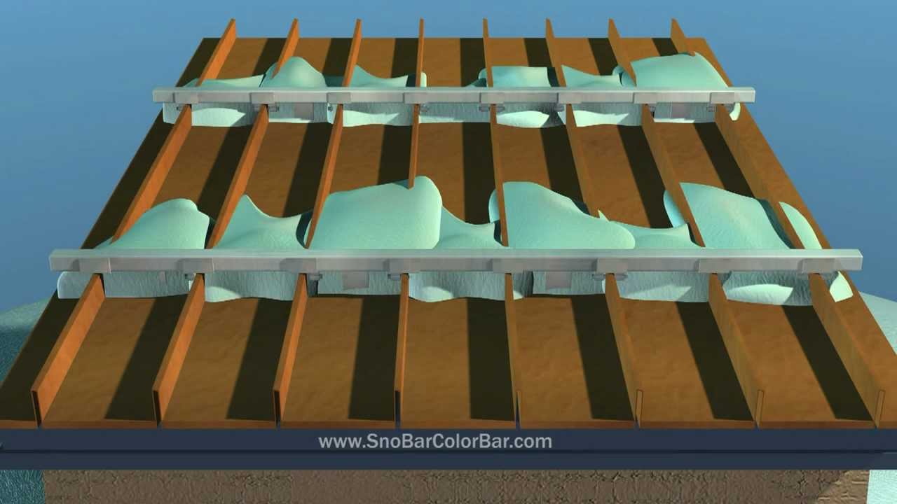
Pad-style snow guards are small, individual units that are produced from polycarbonate or metal. These guards can be mounted mechanically or with adhesive (ONLY when using polycarbonate styles). A snow rail system consists of 6' or 12' long metal bars that are attached to your roof using clamps (for use with standing seam roofing) or brackets (for use with screw down roofing). A bar system normally requires fewer rows but is generally more expensive. Regardless of the system you choose, we never advise installation in isolated areas like above doorways, roof vents, chimneys, or HVAC systems. A proper layout will cover the entire length of the roof and will likely require several rows up the slope for equal weight distribution.
Screw-down installation can normally be done year-round using either the 1.5” Master Driller screws or the 2” Master Gripper screws and the NovaFlex MR150 sealant. Installation with the Surebond SB-190 adhesive must be given approximately 28 days at 50 degrees (fahrenheit) or above to achieve a full cure. In both cases, it's recommended to install your snow retention system before the winter season to ensure it is in place before the first snowfall.