SnoBar ColorBar 2 Bar Standing Seam Installation Instructions
How to Install a 2-Bar SnoBar or ColorBar Standing Seam Snow Rail System
These standing seam 2-Bar SnoBar and 2-Bar ColorBar installation instructions explain how to assemble RoofClamp/RC-2B brackets, position the first row and any additional rows, install the standing seam snow rail bars, add optional IceStoppers, and complete SnoBar butt joints or ColorBar splice connections on compatible standing seam metal roof panels.
- Required parts and tools for 2-bar SnoBar/ColorBar installation
- Standing seam row layout and clamp placement
- RoofClamp/RC-2B assembly and torque requirements
- Two-bar installation steps for SnoBar and ColorBar
- Optional IceStopper installation
- SnoBar butt joints and ColorBar splice connections
- Design conditions and snow retention safety notes
Before Installing the SnoBar/ColorBar 2-Bar System
Read and fully understand all warnings, instructions, regulations, and design conditions before use. Always make sure the roof panels are properly attached to the structure at a fixed point. Standing seam roof clips normally do not provide a fixed point for floating roof panels. The standing seam panels must be attached with enough fasteners to withstand the added load created by retained snow. If unsure, consult with a professional metal roofing installer.
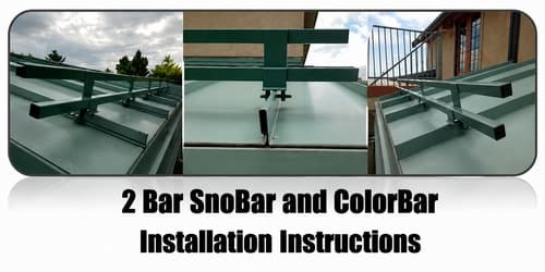
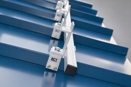
SnoBar/ColorBar 2-bar standing seam snow rail system installed on a metal roof.
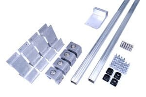
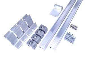
System Parts
Verify quantities of the parts against the packing slip. The system should include:
- RoofClamps with cup tip set screws, top bolts, and washers
- RC-2B brackets
- Bars
- Self-drilling tek screws
- End caps, only for SnoBar
- Splice connectors, only for connecting multiple ColorBars
- Optional IceStoppers, if ordered with the project
RoofClamps, RC-2B brackets, bars, tek screws, end caps, splice connectors, and optional IceStoppers.
2-Bar SnoBar component example.
2-Bar ColorBar component example.
Required Tools
- Rubber Mallet for installing SnoBar plastic end caps
- Drill gun with 3/8" nut driver for driving tek screws
- Torque wrench that reads in inch-pounds
- 3/16" Allen bit for tightening set screws
- 9/16" socket for tightening RoofClamp top bolts
- Flex pivot bit for drill gun to help on shorter seams
- Tape measure
- Hacksaw
- Deburring file
- Pencil
Determine Layout of Rows
Refer to the recommended Spacing For SnoBar on Standing Seam Metal Roofs. A preliminary basic layout is one row 12" up from the eave, or over the load-bearing wall, with all additional rows spaced evenly up the slope.
Example: if the roof is 26'-0" from eave to ridge and two rows are being installed, place the first row 12" up from the eave, or over the load-bearing wall, and place the second row at 13'-6" from the eave edge, or 12'-6" from the first bar.
Safety Warning: Make sure all workers are properly harnessed and anchored to the roof according to OSHA fall protection guidelines. Never use the SnoBar/ColorBar system as a tie-off point.
Important Installation Rules
- Never extend the bar more than 3" past the last clamp at the end of a row or where a row terminates in a valley.
- Bars may need to be cut to length depending on panel width. Do not discard cutoffs until the job is completed.
- Short sections of SnoBar or ColorBar must span at least two seams.
- A short bar clamped to a single seam is not acceptable and will fail.
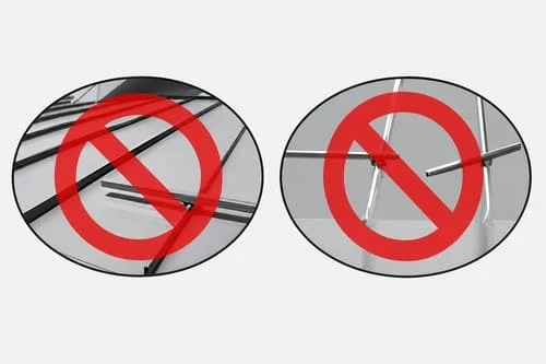
Incorrect bar overhang and incorrect short bar clamped to only one seam.
Installation Instructions
1. Assemble the RoofClamp/RC-2B Assembly
Install all three set screws into each RCT clamp with the cupped tips pointing inward toward the seam. Leave just enough room between the screw tips for the clamps to slide over the seam.
Mount the RC-2B bracket on top of the RoofClamp so the large hole in the RC-2B bracket aligns with the threaded hole on top of the RoofClamp. The four smaller holes on the face of the RC-2B bracket should face upslope. Use the supplied top bolt and washer to attach the RC-2B bracket onto the RoofClamp with a 9/16" socket. Torque the top bolts to 90 in/lbs.
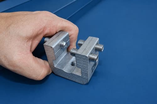
Set screws installed into RCT clamp and RC-2B bracket mounted on top of RoofClamp.
2. Mark the First Bar Section
Based on the manufacturer’s recommended spacing layout, measure 12" to 18" up the seam from the eave. If there is an overhang, place the first row over the load-bearing wall. Mark the farthest seam starting at the left with a pencil.
Mark the same distance from the eave on the seam just short of the length of the bar being installed. For example, when installing a full 12' section of bars, the second mark should be just short of 12' from the first mark. Be sure the two seams are not wider than the bar length being installed. Do not place clamps over clips whenever possible to avoid restricting thermal expansion of the panels.
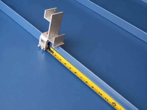
Measuring and marking the standing seam for the first RoofClamp/RC-2B assemblies.
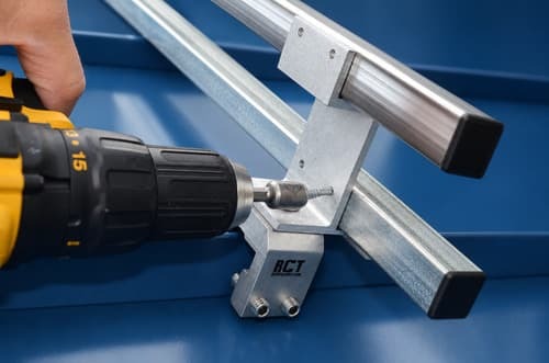
3. Install the First Two RoofClamp/RC-2B Assemblies
Set the first RoofClamp/RC-2B assembly onto the farthest left seam of the bar section at the first pencil mark. Hand tighten the set screws to the seam, making sure the clamp is centered and the bottom of the clamp is pressed down tightly to the top of the seam.
The four holes in the bar receiver section of the RoofClamp/RC-2B assembly should face upslope when properly mounted onto the seam. While applying downward pressure on the assembly, torque the three set screws in the RoofClamp to 90 in/lbs. Repeat this step to install a second RoofClamp/RC-2B assembly on the farthest right seam marked in Step 2.
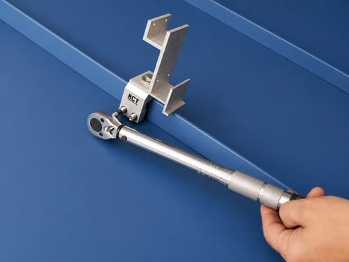
RoofClamp/RC-2B assembly centered on seam with set screws being tightened.
4. Use the Bar as a Straight Edge
Place a full section of bar into the lower receiver of the two RoofClamp/RC-2B assemblies. Do not attach the bars to the assemblies yet. This bar section is used as a straight edge to install the remaining RoofClamp/RC-2B assemblies for that bar section.
The remaining assemblies should only be set in place with the set screws hand tightened. Once all RoofClamp/RC-2B assemblies in the bar section are installed, torque all set screws to 90 in/lbs while applying downward pressure to the bar.
Bar placed in lower receivers as a straight edge for aligning additional assemblies.
5. Install SnoBar End Caps
If using 1" square SnoBar, install the supplied plastic end caps at each end of the SnoBar. Deburr any field-cut bars before installing end caps.
If using aluminum ColorBar, disregard this step.
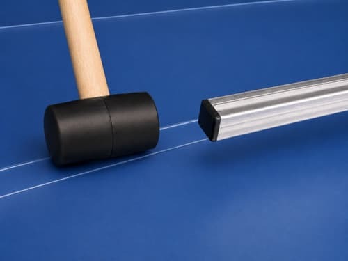
Plastic SnoBar end cap being installed with a rubber mallet.
6. Install the Two Bars
Set two bars into the RoofClamp/RC-2B assemblies. Do not extend the bars more than 3" past the last RoofClamp/RC-2B assembly at the end of the row. Make sure each bar is seated tightly in both RoofClamp/RC-2B assemblies.
Apply downward pressure to the bars while installing the four tek screws through the back of the RoofClamp/RC-2B assembly into the SnoBar or ColorBar. Follow the same procedure for each clamp as you progress down the section of bar.
Repeat Steps 1 through 6 for each full section of bar until the row is completed.
Two bars seated in RoofClamp/RC-2B assemblies with tek screws installed through the back of the bracket.
7. Install Optional IceStoppers
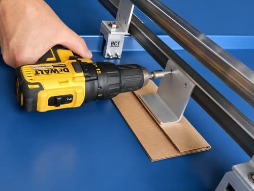
When optional IceStoppers are installed, the short leg of the IceStopper should face upslope with the tek screw holes lining up with the upslope side of the lower bar. If installing one IceStopper per panel, center it between clamps.
Place a piece of cardboard under the IceStopper to provide a small space between the IceStopper and the panel. Hold the IceStopper tightly to the upslope side of the lower bar and install two tek screws while applying downward pressure. On panels 18" to 24" wide, use two IceStoppers spaced equally between panel seams. If using ColorBar on panels with seam spacing wider than 24", use three IceStoppers. If IceStoppers were not ordered with the original system and snow or ice slides under the bars, they can be added later. IceStoppers do not always come with pre-drilled holes.
Optional IceStopper installed against the upslope side of the lower bar.
8. SnoBar Butt Joints and ColorBar Splice Connections
For SnoBar: butt joints should always be centered in the panel valley with no more than a 2" gap between butted ends. Some panels require the bars to be cut to obtain correct seam spacing.
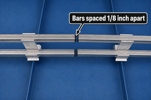
For ColorBar: the supplied splice connectors create a continuous run of bar, so the bar ends should be no farther than 1/8" apart. ColorBar butt joint connections can be made anywhere along the row other than inside the clamp, as long as the splice connectors are properly installed with one tek screw each.
SnoBar butt joint centered in panel valley.
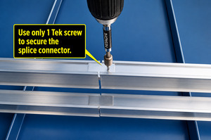
ColorBar splice connector installation.
9. Install Additional Rows
Space additional rows of SnoBar or ColorBar evenly up the slope, always measuring from the eave edge according to the manufacturer’s recommended spacing layout. This provides better protection against snow and ice slides while helping balance structural loading across the roof structure.
For spacing assistance, call 800-766-5291.
Design Conditions
- All loads incurred by the SnoBar/ColorBar system transfer to the panels. Proper panel attachment to the substrate or structure is necessary to prevent roof panels from sliding under snow load. New and existing structures must be evaluated to ensure they can withstand retained snow loads. If there is an overhang at the eave edge, make sure the overhang can hold the accumulated snow load; otherwise, the first row should occur at the bearing wall.
- It is not recommended to place the SnoBar/ColorBar system in isolated areas such as over doorways, vents, and partial roof areas. Call for special design considerations in these areas.
- No snow retention system is capable of retaining 100% of snow and ice from falling off the roof. The system is designed to mitigate the dangers of sliding snow and ice.
- The roof system should be a minimum of 24-gauge steel and have a seam height of at least 1". Do not use the SnoBar/ColorBar system on seams with separate seam covers or batten strips.
- Clamp spacing varies depending on seam spacing from 12" on center up to 42" on center. Clamps should be placed at every seam so the load is distributed evenly to every roof panel.
- The designer, architect, installer, or owner should know the local snow loads, climatic conditions, roof slope, roof orientation, potential drifting, and roof design before installing a SnoBar or ColorBar system.
- System layout is calculated using panel length, ground snow load, roof slope, snow loading, and areas needing protection from falling snow. More than one row of SnoBar/ColorBar may be needed. For design service, call 800-766-5291 or email support@snojax.com.
- Unforeseen conditions such as drifting, ice, or uncharacteristic snowfall may occur. When extremes are reached, snow and ice should be physically removed from the roof. Snow retention systems do not prevent snow drifting on overhangs or cornices.
Action Manufacturing LLC and/or IceBlox, Inc. is not responsible if system failure occurs from improper installation, improper panel attachment, improper roof system installation, or inadequate spacing layout of the SnoBar or ColorBar system.
It is the sole responsibility of the designer, architect, installer, or owner to assess the suitability of using the SnoBar or ColorBar systems based on the design considerations above.
Need Help With Layout or Spacing?
SnoBlox-Snojax provides layout assistance for SnoBar and ColorBar snow retention systems. For help with standing seam snow rail row placement, or project-specific layout questions, call 800-766-5291 or email support@snojax.com.
2 Bar SnoBar and ColorBar Installation Instructions FAQ
Yes. Install a 2-bar SnoBar or ColorBar system according to the factory-recommended spacing. A basic starting point is one row 12" up from the eave, or over the load-bearing wall when an overhang is present, with additional rows spaced evenly up the slope.
SnoBar or ColorBar should never extend more than 3" past the last RoofClamp/RC-2B assembly at the end of a row or where a row terminates into a valley.
No. A short section of 2 Bar SnoBar or ColorBar must span at least two seams. A short bar clamped to a single seam is not acceptable and can fail.
The RoofClamp top bolts and the three set screws in each RoofClamp should be torqued to 90 in/lbs during installation.
The four smaller holes on the face of the RC-2B bracket should face upslope when mounting the RoofClamp/RC-2B assembly on the standing seam.
The two bars are seated tightly in the RoofClamp/RC-2B assemblies. Four Tek screws are installed through the back of each RC-2B bracket into the SnoBar or ColorBar while applying downward pressure.
Install SnoBar end caps on each end of the 1" square SnoBar. Deburr any field-cut bars before installing the plastic end caps. This step does not apply to the aluminum ColorBar.
Install optional IceStoppers with the short leg facing upslope and the Tek screw holes aligned with the upslope side of the lower bar. Hold the IceStopper tightly against the lower bar and install two Tek screws while applying downward pressure.